Mastering the use of Revit and BIM was one of the reasons I was attracted to this course. I have been therefore super-motivated to get stuck in to this task and start getting to grips with this program!
At the end of the first two weeks, I am a little struck with the complexity of the software and the range of configurations. To me this is a totally new way of constructing a 3D model. Creating geometry in AutoCAD and Inventor seems to be much more intuitive, and I see this can be imported into a Revit family if desired. However, I can see the usefulness of the way the model is constructed in BIM as opposed to regular drawing.
The 2D drawing output from my model is not quite as refined as I would like yet. Since the course material so far has only covered basic modelling, I have not attempted to refine these 2D drawings in any way other than to make sure the geometry produced by the model is correct. I see there are display and annotation settings which can do this, which I hope to go into at a later point.
Similarly, rendering and 3D imaging settings have also been ignored with the hope of learning more later. I hope I will look back on this week’s blog entry in the future and consider this model raw and basic! At this point, getting to grips with this seems anything but simple. ‘My first Revit project’ is therefore a nod to that this really is a kind of ABC-123 type introduction on my part, and about learning to crawl through the jungle of modelling options available in this software!
The task:
Create a BIM model of the house below from a set of 2D drawings using BIM objects from standard suppliers.
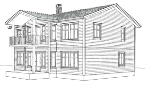
Full dimensioned 2D drawings, including plans, sections and elevations have been made available. Additionally, specific doors are to be used from the NorDan and Swedoor product ranges for which models from BIMObject are available for use in the model.
In addition, a wooden staircase is to be drawn using the built-in Revit stair tool.
As extra challenges, the following may be included:
- Chimney
- Custom wall type, as real as possible using external sources
- Custom floor type, as real as possible using external sources
Wall thickness
Glava insulation was used as a reference point for giving a suitable wall build-up. The studwork dimension on the provided drawings was 148mm, which I combined with a 48mm outer wall panel, and a total of 50mm for external and internal finishes to give a total of 246mm.


Floor thickness
The same principle was applied to floors as to the walls. Both the ground floor and dividing floor between level 1 and 2 were taken from the Glava manual, using the overall depth given on the original section drawing (and disregarding current U-value requirements).
 To create the ringwall foundation, I began with the Structural Foundation: Wall tool. A problem which came up here was that despite setting this to 200mm blockwork, the software wanted to extend the thickness of the ring wall to match the wall above, whereas this should be level with the core above.

I later changed the ringwall to a standard wall, with a thickness of 200mm in concrete blockwork, ignoring any detail for damp protection at this stage. I also included a foundation under this wall. The problem here is that the cladding does not overlap the joint as it should.
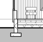 It seems like Revit has a lot of functions which aren’t necessarily obvious or easy to find. Extending this cladding downwards was straightforward in the end, but not before several hours of searching through and watching various tutorials. This one eventually explained how to get the cladding to overlap by unlocking the bottom of the preview in the ‘Modify Vertical Structure’ function in the ‘Edit Assembly’ view. This section could then be manually edited in section view.
Stair
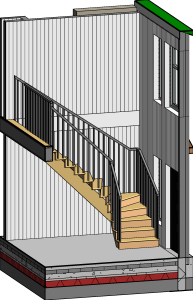 One of the most useful features I have learned so far is how easy it is to create cutaway 3D views illustrating various aspects of the construction, using the Selection Box tool.
This stair tool created some headaches in generating the desired form! I had to adjust the riser and tread dimensions in order to be able to position this to fit with the door and floor openings. I wanted also to make sure it complied with PBL for stair dimensions, which states a minimum tread of 250mm. Interestingly, unlike British regulations, there is no maximum riser height (220mm for private dwellings). With 15 risers, the height worked out at being 197mm each and it therefore satisfies both Norwegian and UK building regulations. The stair tool in Revit makes controlling these parameters quite simple, compared to having to calculate and draw this manually.
A stair can be a thing of beauty and is often a personal signature of
the architect! I have not yet acquired control over the design of the actual stair beyond the basic parameters, so much more practice with this is required before I can create a custom design.
Chimney
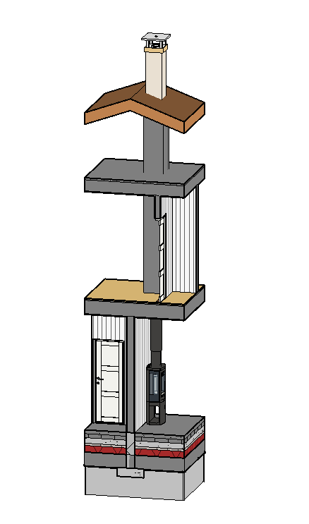
This was also another useful place to create a cutaway view. Initially, whilst drawing the walls I marked out the position of the chimney with a column stretching through all floors. This enabled me to place the bedroom walls in a non conflicting position before returning to this in more detail.
I later found a fireplace and pre-fabricated chimney on BIMobject, and positioned these on the model. The pipe connecting them was something of a quick fix, a simple cylinder created in Component>Model in-place and assigned the same colour as the Nordpeis unit (as displayed in their marketing material, but not included in the model). This extends to roof level to connect to the chimney.
On the floors above, I boxed in the pipe with a wall casing. I looked at various chimney stack options, for example here by Schiedel to get an idea of various construction options. I was satisfied with this as a simplification ahead of any further detailed design which may be required later at a construction phase.
Kitchen
I wanted to see how components worked in Revit, and decided to try and use the included Revit kitchen units to create a functional layout. I tried drawing this same kitchen initially with units found on BIMobject from Ballingslöv. However, the models weren’t as easily configurable as I hoped and looked untidy in plan.
It seems the advantage with the built-in components is that they are designed especially for use with Revit and have a readily refined appearance in plan and elevation. They are a little limited in style and appearance, but serve to illustrate a purpose or intention.
For the kitchen design, I installed an additional wall where appliances and tall cupboards could be recessed. Also, an kitchen island works well in this space with a breakfast bar.

These first two weeks of using Revit has brought me to a point where I am able to construct a reasonable looking building model. From here I will want to further my knowledge of detailed construction, and be able to refine and control the model to give useful data. I am also very curious about how to create custom geometries or better integrate manufacturers products. I am particularly curious about how it might be implemented in the renovation of heritage projects, and have located some relevant tutorial series to spend the time in Corona-lockdown with!
For now, here are some images from my first attempts at drawing in Revit:

My attempt to replicate the original perspective drawing

Level 1 Floorplan

Level 2 Floorplan
